
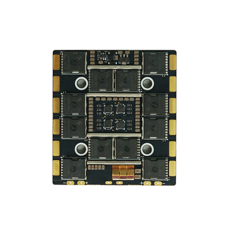
A 4 in 1 ESC and flight controller can share mounting dimensions while serving different electrical roles. In a civil multirotor using the BL-S 100A ESC and F722 BF controller, the battery path, regulated peripheral rails and physical stack each need a separate integration decision. Their published specifications establish useful boundaries for that work, with the narrower component range governing a shared supply.
The BL-S 100A sets the shared battery-range ceiling
The BL-S 100A ESC lists a 4–8S LiPo input, while the F722 BF lists 3–12S LiPo input. The common stated cell-count range is therefore 4–8S when both boards are supplied directly from the same pack. The controller’s wider range remains a controller capability rather than a higher-voltage rating for the assembled stack.
The BL-S 100A input and current specifications identify the board that drives the motors. A 12S supply selected solely from the F722 description lies outside that ESC’s published input range. Keep the battery connection, motor supply and regulated outputs distinct in the system diagram, with every directly connected device assessed against its own permitted input.
Cell-count overlap is the first screen, followed by the actual pack’s voltage limits and the ratings of the remaining connected hardware. The selected motor, propeller and duty cycle also determine the current the propulsion system asks the ESC to carry. These relationships make the complete component combination the object of integration, rather than either board in isolation.
The F722 listing leaves a regulated-rail discrepancy to resolve
The BL-S 100A is listed without a BEC. The F722 BF description advertises 5 V / 3 A and 12 V / 2.5 A outputs, but its featured board photograph shows 9 V pad labels. The available material does not establish whether the photograph and description represent the same board revision. Treat the higher-voltage peripheral rail as unresolved until revision-specific documentation identifies its voltage, current limit and pin assignment.
The F722 BF supply and expansion-interface listing therefore starts a document review rather than completing a connection plan. Its listed six UART interfaces describe communication resources, which serve a different purpose from regulated power. Identify power, ground and signal separately against the documentation for the board actually supplied; a peripheral requiring 12 V cannot be assigned to a photograph’s 9 V pad on this evidence.
- BL-S 100A motor channels — 100 A × 4, listed continuous current: this describes four ESC channels, not a regulated supply available to cameras or receivers. Apply the current rating with its actual installation and thermal conditions.
- F722 BF 5 V rail — 3 A advertised output: the stated pair gives an arithmetic 15 W, conditional on the description applying to the supplied revision. This is neither measured peripheral consumption nor a verified continuous installation rating.
- F722 BF higher-voltage rail — revision unresolved: the description and photographed pad labels differ. Reserve this connection in the design rather than selecting either voltage as established hardware behavior. A combined rail-power budget also needs a documented simultaneous-loading envelope.
Keeping these roles separate also clarifies the current sensor. The ESC lists current-sensor support, which is a feature to integrate with a compatible measurement path. Converting its output into useful logged current requires the actual interface and calibration information. A supported sensor and a live number on a screen represent different stages of that implementation.
A 30.5 mm mounting match leaves the rest of the stack to resolve
The BL-S 100A and F722 BF both list a 30.5 × 30.5 mm mounting pattern; the ESC additionally lists a 41 × 46 mm board size and 14 g mass. The shared hole pattern establishes one geometric relationship. Board edges, components, connectors, supports and routed cables define the complete installed envelope.
Draw the two board outlines at the chosen mounting centers before locating surrounding structure. Include connector access and the path by which each cable enters or leaves the stack. A cable that fits the bare board can occupy the space needed by a support or adjacent component after assembly. The board dimensions provide a first boundary, while the actual connector and support geometry determine the remaining layout.
The same drawing should distinguish electrical identity from physical proximity. A conveniently placed connector needs the correct pin assignment, voltage and signal relationship for the intended pair. Route the motor-power and peripheral connections according to those documented roles, with clear identification during assembly and maintenance.
Close the integration at the interfaces, then assess the installation
For this BL-S 100A and F722 BF combination, the working architecture begins with a shared input constrained to the ESC’s published 4–8S range, separate controller-provided peripheral rails and a mounting layout developed beyond the common hole pattern. This gives the integrator three concrete boundaries to carry into the full aircraft design.
The remaining implementation work is specific: obtain the applicable wiring and rail-loading information, then assess the installed electrical and thermal behavior under the intended civil mission. Keep any connection diagram tied to the identified board versions. A resolved interface allows the propulsion system and peripheral system to be evaluated together without treating their ratings as interchangeable.