
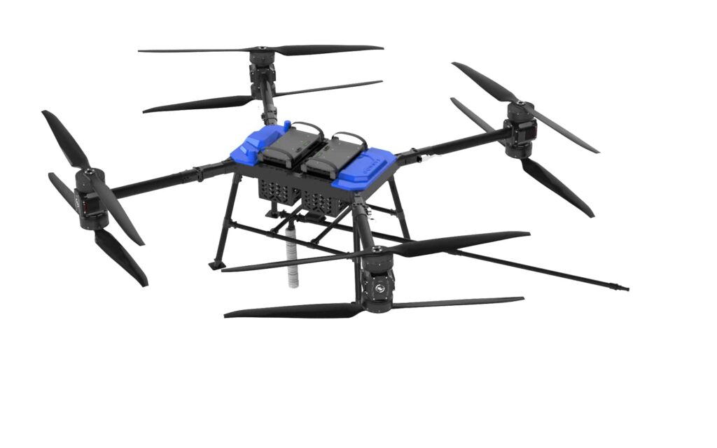
A heavy lift cargo drone reaches its launch area through a ground-handling system: vehicle, unloading point, doorway, turning space and staging position. For the MRT30 and MRT100, payload capacity answers a different question from the space and equipment needed along that route. Start the selection with the aircraft’s transport configuration and handling mass, then connect that arrangement to the required cargo mission.
Folding changes the MRT100 envelope in more than one direction
The MRT100 has published unfolded dimensions of 1900 × 1900 × 700 mm and folded dimensions of 1045 × 945 × 975 mm, in the original listed order. Folding reduces the first two listed extents while increasing the third by 275 mm. A route designed around only the smaller pair therefore leaves an important part of the envelope unresolved.
The MRT100 folding and dimensional specifications provide the starting geometry for a transport layout. Preserve that order until a drawing establishes the axes and the permitted transport orientation. If the 975 mm extent lies vertically in the selected orientation, overhead clearance follows that extent plus the actual support arrangement; another orientation needs its own supported handling method.
A transport cradle, pallet or protective enclosure adds its own dimensions. Sketch the complete transported assembly through the narrowest door, the turn immediately beyond it and the unloading position. A rectangle that passes straight through a doorway can still require additional space as it rotates, especially beside a wall or parked equipment. Use the assembled envelope for that path rather than the bare-aircraft footprint alone.
MRT30 and MRT100 mass entries describe different handling starting points
The MRT30 is listed at 23.6 kg empty and approximately 32.7 kg with its battery; the MRT100 is listed at 52 kg without a battery. These descriptions support separate handling calculations because their battery inclusion differs. For the transport system, add the equipment actually moved together: aircraft, installed battery where applicable, support frame and retained accessories.
The MRT30 mass, battery and wheelbase entries also list a 14S 28000 mAh battery, a 1495 mm wheelbase and a 30 kg maximum payload. The MRT100’s maximum payload is 100 kg. Payload belongs to the airborne mission requirement; the mass carried by a trolley or unloading aid follows the actual ground configuration.
| Model and physical question | Published entry and its use in the layout |
|---|---|
| MRT30: ground-handling mass, kg | 23.6 kg empty or approximately 32.7 kg with battery; choose the entry matching the transported configuration and add its supports. |
| MRT30: wheelbase, mm | 1495 mm describes the listed wheelbase; establish the complete outer transport envelope separately. |
| MRT100: battery-excluded aircraft mass, kg | 52 kg excludes the battery; include the actual installed pack and handling fixtures in the supported load. |
| MRT100: folded envelope, mm | 1045 × 945 × 975 mm retains the published order; map the axes and orientation before assigning door or overhead clearances. |
This comparison keeps the ground equipment’s supported load distinct from the aircraft’s payload capability. It also separates a dimensional quantity such as wheelbase from the outer shape that a doorway encounters. That distinction makes the smaller model a candidate for assessment, rather than an automatic solution to every restricted route.
A usable handling route includes turns, personnel and staging space
Ground movement of the MRT100 requires clearance for the actual aircraft-and-support assembly wherever it passes or turns. In a US workplace using mechanical handling equipment, OSHA’s material-handling clearance requirement addresses aisles, loading docks, doorways and turns, together with keeping passageways clear. It supplies a workplace constraint, not a numerical aircraft operating buffer.
Lay out unloading, temporary storage and the final staging position as connected spaces. The trolley needs a route, the operator needs a working position, and the support arrangement needs room for any permitted change from transport to deployed configuration. Keeping the moving assembly and nearby stored equipment on the same drawing exposes conflicts earlier than comparing a doorway width with one aircraft dimension.
The staging area then becomes the boundary between ground logistics and the separately assessed flight operation. Ground-route clearance and aircraft operating clearance have different purposes. Retain both in the site plan, with the applicable operating requirements handled through the project’s actual aviation and site procedures.
Choose the aircraft-and-handling arrangement together
The MRT30 and MRT100 suit different stated payload classes, but their practical selection also depends on the route from delivery vehicle to staging area. Use the required cargo mission to establish the capacity class, then assess the supported mass, complete transport envelope and permitted deployment arrangement as one system.
For this ground route, carry the dimensions in their published order until the transport orientation is established. Use the mass entry that matches the installed battery and add the actual support arrangement, then assess that complete assembly through the path and staging position. These conditions define what the layout calculation represents; keep the separate flight-area assessment attached to its own operating configuration.