
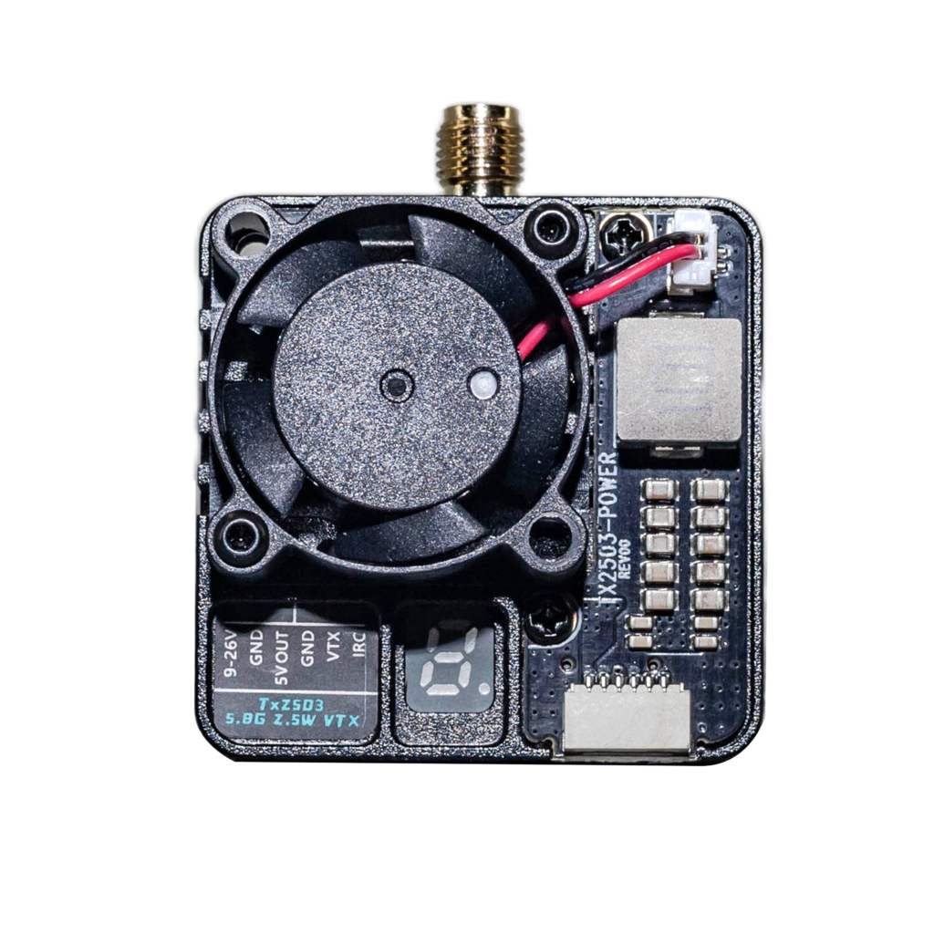
A 7 W RF output figure looks simple on a specification sheet.It isn’t.
The number tells you how much radio-frequency power the transmitter can put toward the antenna at its maximum setting. It does not tell you how efficiently the UAV uses that power, how much electrical power the transmitter consumes, how much heat the electronics must reject, or whether running at 7 W actually improves the link enough to justify the additional load.
That distinction gets buried surprisingly often. A transmitter rated for 7 W maximum output is better understood as a controllable RF subsystem, not a device that should simply be left at maximum power from takeoff to landing.
Peak RF Power Creates a Thermal Problem. The basic engineering problem is unavoidable: electrical input power and useful RF output power are not the same thing.If a transmitter produces 7 W of RF output, the electronics still consume more electrical power than the amount delivered as RF. The difference has to go somewhere. In practical hardware, much of it becomes heat.
That heat has consequences.The transmitter is mounted inside a UAV where space is limited, airflow can change dramatically with flight attitude and speed, and other electronics may already be generating substantial thermal load. Treating maximum RF output as a permanent operating condition therefore creates a problem that has nothing to do with marketing claims about transmission distance.
The problem is temperature.Wait, let me rephrase that—temperature is only part of it. The real issue is the chain connecting RF output, electrical consumption, thermal loading, and the aircraft’s available power budget.
At 7 W RF output, the transmitter is operating near the upper end of its RF power capability. If the link budget does not require that level, continuously using it simply means the UAV is carrying additional electrical and thermal load without a corresponding system-level benefit.That is why multi-level power adjustment matters.It gives the operator another variable to control.
Maximum Power Should Be a Setting, Not a Religion.There is a persistent habit in drone hardware discussions: more RF power is automatically treated as better.That is an incomplete engineering argument.A wireless link has requirements. If the required link quality can be maintained at a lower transmitter power, reducing RF output can also reduce the electrical and thermal burden imposed on the aircraft.
The useful operating point therefore depends on the actual flight condition.A transmitter flying close to the receiver does not necessarily need the same RF output as one operating at the edge of its available link budget. Those are different operating conditions, even though the hardware is identical.
The 5.8 GHz 7 W video transmitter addresses this through multi-level power adjustment rather than forcing a single maximum-power operating mode.That sounds like a small feature.It isn’t.For an embedded UAV subsystem, controllability is often more useful than an impressive peak specification.
The transmitter can be operated at a lower power level when the link budget allows it, reducing unnecessary electrical consumption and thermal loading. When higher RF output is actually required, the available 7 W maximum remains part of the operating envelope.
That is a much more realistic interpretation of a 7 W transmitter.The Battery Interface Is Part of the RF Design.Another easy mistake is treating the transmitter as an isolated radio module.On a real UAV, it is part of the electrical architecture.
The 5.8 GHz transmitter accepts a 9–26 V DC input range. That covers common 3S–6S UAV battery architectures without tying the module to one specific battery voltage.But a wider input range does not magically make the power electronics simpler.Quite the opposite.
The input stage has to tolerate different supply conditions while maintaining stable operation across that range. A transmitter designed around a single nominal battery voltage has a narrower electrical problem. A module intended to work across 9–26 V has a broader one.That is the trade.The advantage is platform compatibility. The engineering cost moves into the power-input stage.
Here’s the thing: integration problems rarely appear on the first line of a product specification. They appear when someone tries to bolt the module into an existing aircraft and discovers that the battery architecture, mounting geometry, connectors, and power requirements do not line up.A transmitter that accepts common UAV supply architectures removes one of those integration constraints.
It does not remove the need for proper power design.30.5 × 30.5 mm Is More Important Than It Looks.The mechanical interface is similarly unglamorous.The transmitter uses a 30.5 × 30.5 mm mounting pattern and an MMCX antenna interface.Neither specification sounds particularly exciting.
Both can save engineering time.The 30.5 × 30.5 mm mounting pattern follows an established FPV integration convention, allowing the transmitter to fit into existing UAV stack arrangements without forcing an entirely new mechanical layout.That matters because drone integration is rarely just about whether a component technically works.
A component has to fit.It has to mount securely.Its antenna connection has to be accessible.Its wiring has to reach the correct locations.Its electrical input has to match the aircraft.And the resulting assembly still has to coexist with the rest of the flight electronics.
Changing one mounting dimension can turn a straightforward integration job into a mechanical redesign. Following an established mounting pattern avoids creating that problem unnecessarily.
The MMCX interface serves a similar purpose on the RF side. It provides a defined physical antenna connection rather than requiring a custom mechanical interface for every aircraft installation.This is not glamorous engineering.It is useful engineering.
5.8 GHz Does Not Mean “Maximum Range”.The most misleading way to describe a high-power video transmitter is to reduce the entire device to a single distance number.A transmitter does not operate in a vacuum.
Actual link performance depends on the complete RF system and operating environment. Transmitter output is one variable. The antenna system, receiver, installation, interference environment, orientation, and available link margin all affect what happens in the field.The company experience behind this 5.8 GHz 7 W transmitter deliberately does not turn the 7 W figure into an unsupported maximum-range promise.
That restraint is technically important.A higher RF output can provide more available transmit power, but it does not mean the system will automatically deliver a fixed range under every flight condition.Look at the architecture instead.The hardware provides a 7 W maximum RF output, adjustable power levels, a 9–26 V input range, a standard 30.5 × 30.5 mm mounting pattern, and an MMCX antenna connection.Those are engineering parameters.They tell you how the module is intended to behave and how it is intended to integrate.A single range number would tell you much less.
The Real Design Trade-Off Is Control.The interesting part of this transmitter is not the 7 W figure by itself.It is the decision to make that figure controllable.Extreme lightweighting, maximum RF output, minimum electrical consumption, and low thermal load are not independent goals. Push one aggressively and another often becomes harder to manage.For a UAV, this matters because the aircraft itself is a tightly coupled system.Electrical power is finite. Thermal capacity is finite. Physical space is finite.
A transmitter that can operate at several power levels gives the system a way to adapt instead of forcing one operating point onto every mission.That is a much more defensible engineering choice than simply chasing the highest possible output number.If the aircraft is operating under conditions where lower RF power is sufficient, there is little engineering reason to insist on maximum output merely because the hardware can provide it.If the link requirements demand more output, the 7 W ceiling is available.Simple.But useful.
Integration Usually Beats Specification-Sheet Theater.The old assumption that a better transmitter is simply the one with the biggest number is increasingly difficult to defend once the hardware is actually installed into an aircraft.A UAV does not carry isolated specifications.It carries a collection of interacting subsystems.
The transmitter draws power from the aircraft. Its RF output contributes to the wireless link. Its inefficiency becomes thermal load. Its physical dimensions affect stack integration. Its antenna connector affects RF installation. Its input range determines which battery architectures can be used without adding unnecessary conversion hardware.
Every one of those decisions creates a trade-off somewhere else.That is why the 5.8 GHz 7 W video transmitter is better understood through its complete operating envelope than through the phrase “7 W.”The maximum output provides capability.Multi-level adjustment provides control.The 9–26 V input provides platform compatibility.The 30.5 × 30.5 mm pattern reduces mechanical integration work.The MMCX interface provides a conventional RF connection.
None of these features alone makes a UAV system work.Together, they define how the transmitter behaves as an actual aircraft subsystem.And that is the part worth paying attention to.Peak power is easy to print on a specification sheet.
Managing that power without turning the aircraft’s electrical and thermal architecture into a mess is the harder engineering problem.