
A flight controller is not made better by simply adding more interfaces. That sounds obvious, yet a surprising amount of UAV hardware discussion treats integration as if it were free. Add Bluetooth. Add UARTs. Add GPS support. Add telemetry. Add another regulated voltage rail. Put everything on the same board and call it a more advanced flight controller. The PCB does not care about the marketing language.
Every additional function consumes routing space, power budget, thermal capacity, firmware resources, or some combination of all four. The F405 Flight Controller Bluetooth version is interesting for exactly that reason: its engineering problem is not simply how to run an STM32F405 and an IMU. It is how to fit a relatively dense peripheral architecture into a familiar 30.5 × 30.5 mm multirotor footprint without turning the board into an integration headache.
The MCU Is Only the Starting Point. The F405 platform is built around the STM32F405 MCU, paired with an ICM42688 IMU and an AT7456E OSD. On paper, that sounds straightforward. It isn’t the processor that makes the architecture interesting. The harder part is everything connected around it.
A conventional minimalist flight controller can devote much of its PCB area to the processor, IMU, power filtering, and a limited number of communication interfaces. Once the board is expected to handle six UART ports, I2C, ESC telemetry, Bluetooth, and multiple regulated outputs, the design becomes a routing exercise as much as a flight-control exercise.
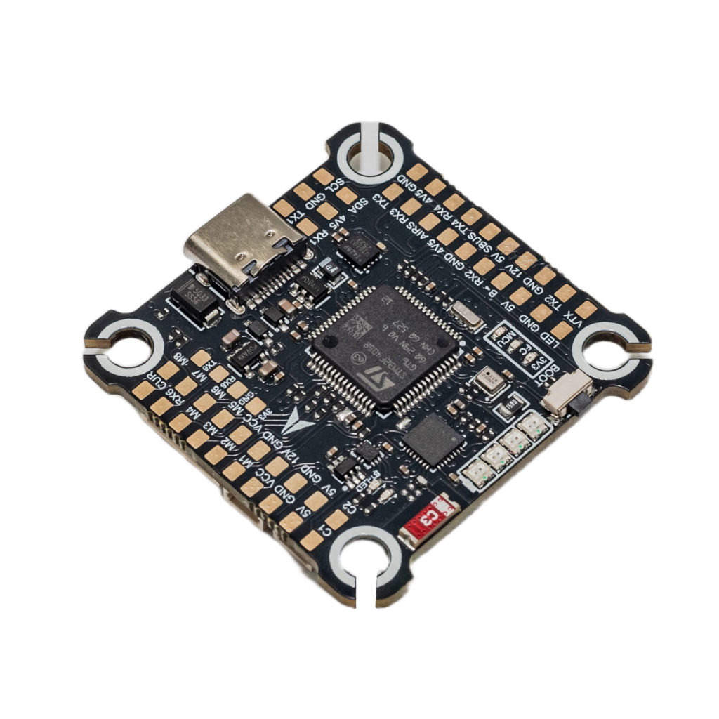
Look, this is where simplistic specification sheets usually lose the plot. Saying “six UARTs” tells you what the board exposes. It does not tell you what it costs electrically to expose them while maintaining sensible power distribution, signal routing, connector placement, and noise control. That distinction matters.
The old market-oriented material frames flight-control technology around broad trends such as autonomous systems, AI, data analytics, and integration across different UAV applications. Those categories may describe where the industry wants to go, but they do not explain why a particular controller is physically designed the way it is. A PCB does.
Bluetooth Is an Integration Decision, Not a Free Feature. The Bluetooth version adds wireless connectivity directly to the flight-controller architecture. That changes the board’s job.
Instead of requiring every configuration or peripheral function to be handled through separate external hardware, the controller can act as a more centralized interface for an FPV build. GPS, receiver equipment, telemetry, ESC communication, and video-related hardware can be connected around the controller rather than forcing the aircraft designer to distribute those functions across multiple boards.
That can simplify the aircraft at the system level. It also makes the flight controller more complicated. Wait, let me rephrase that—system simplification often means board-level complication.
The F405 design allocates resources for six UART ports alongside I2C and ESC telemetry. Those interfaces are useful because FPV aircraft rarely remain electrically simple once a builder starts adding navigation, receivers, telemetry, and other peripherals. But every interface introduces routing requirements, pin allocation considerations, and another opportunity for electrical interference or poor board organization.
Bluetooth therefore should not be evaluated in isolation. The relevant question is not “Does it have Bluetooth?” The better question is: What additional system hardware can be eliminated or consolidated because Bluetooth is integrated into the controller? That is an engineering question rather than a feature-count question.
Power Distribution Is Where the Real Work Hides. The electrical input range is specified for 3–6S LiPo power, which corresponds to a significantly wider voltage range than the low-voltage rails used by most onboard electronics. The controller provides dedicated regulated outputs:
5V / 3A
9V / 2–3A
3.3V
This arrangement is useful because different peripherals do not necessarily want the same supply voltage or current capability. But there is no free lunch here.
A 6S LiPo pack can present substantially more voltage than a 5V or 3.3V peripheral requires, so the controller needs appropriate voltage-conversion stages and power-management architecture between the battery input and those rails. Multiple regulated outputs mean additional conversion components, filtering, thermal considerations, PCB area, and routing constraints.
This is one reason extreme lightweighting is not automatically the correct objective for a flight controller. Shaving PCB area or component count sounds attractive until the missing resources have to be replaced with external regulators, distribution boards, or wiring.
Then the aircraft has more parts instead of fewer. Our design choice was therefore not to treat the flight controller as a bare sensor-and-processor board. Some PCB and power resources were deliberately spent on integration because the resulting architecture can support a denser FPV configuration without requiring every peripheral function to live on a separate board.
That is a trade-off. It is not magic. Why Keep the 30.5 × 30.5 mm Mounting Pattern? Because aircraft frames already exist. The 30.5 × 30.5 mm mounting pattern is a familiar mechanical interface in multirotor hardware. Abandoning that constraint would give the PCB designer more freedom, but it would simultaneously reduce compatibility with established frames.
Here’s the thing: unrestricted PCB layout is a designer’s dream and an integrator’s headache. If the board were designed around whatever dimensions best suited its internal routing, the electrical architecture might become easier to arrange. But the customer would potentially need a different frame, mounting hardware, or mechanical adaptation simply to install the controller.
Keeping the established mounting pattern imposes a physical boundary around the electrical design.
The result is a denser board. Six UARTs, I2C, ESC telemetry, Bluetooth, multiple voltage rails, the MCU, IMU, OSD circuitry, and their supporting components all have to coexist inside that mechanical envelope. Routing and component placement consequently become part of the system architecture rather than an afterthought.
That constraint is actually useful when evaluating hardware. A flight controller should not be judged only by the number of functions listed in its specification. The interesting engineering question is how many of those functions can coexist without forcing the rest of the aircraft into unnecessary complexity.
The Old Market Narrative Misses This Layer. The supplied market material spends considerable space dividing UAV flight-control technology into applications such as logistics, fire safety, mapping, broadcasting, and autonomous aircraft.
That information is broad. The F405 Bluetooth architecture is narrow. And that is precisely why the two should not be treated as equivalent evidence.
A market report can describe application categories and projected growth, but it cannot tell you whether a flight controller has enough UART resources for the intended aircraft, whether its power rails can support the attached peripherals, whether the mechanical mounting pattern matches the frame, or whether integration reduces wiring complexity. Those are hardware questions.
The F405 architecture answers some of them directly: STM32F405 processing, ICM42688 sensing, AT7456E OSD, six UART ports, I2C, ESC telemetry, Bluetooth connectivity, 3–6S input, and dedicated 5V, 9V, and 3.3V power rails.
Those details provide much more useful engineering information than vague claims about “next-generation UAV technology.”
Integration Has a Cost. A dense flight controller is not inherently superior to a minimalist one. If an aircraft requires only basic stabilization and a receiver, many of these interfaces may be unnecessary. In that case, the additional circuitry becomes unused capability and additional design complexity.
For a more integrated FPV platform, the calculation changes. When GPS, receiver, telemetry, ESC communication, and other peripherals are part of the aircraft architecture, having communication and power resources centralized on the flight controller can reduce the need for separate supporting electronics and simplify the overall wiring structure.
So the real design trade-off is fairly blunt:
More integration at the flight-controller level means more complexity on the flight-controller PCB. The benefit appears at the aircraft level. The penalty appears during electrical design. That is a perfectly normal engineering trade. The mistake is pretending there is no penalty. What the F405 Bluetooth Version Actually Represents
The F405 Flight Controller Bluetooth version is best understood as an integration-oriented flight-control platform, not simply an STM32F405 board with wireless connectivity added to the feature list.
Its architecture combines:
STM32F405 + ICM42688 + AT7456E OSD + six UARTs + I2C + ESC telemetry + Bluetooth + multiple regulated power rails + 30.5 × 30.5 mm mounting. That combination explains the design priorities.
The controller keeps compatibility with an established multirotor mounting standard while increasing electrical interface density. It accepts 3–6S LiPo input and distributes power through dedicated regulated rails rather than leaving every peripheral to solve its own voltage requirements. It provides enough serial connectivity for a more heavily integrated FPV configuration instead of assuming the aircraft will remain electrically minimal.
None of that makes the physics disappear. It simply moves the engineering work to the place where it can be managed.
And that is the part generic flight-controller descriptions usually fail to explain: good integration is not about putting more functions on a specification sheet. It is about deciding which complexity belongs inside the controller and which complexity should be pushed elsewhere in the aircraft.