
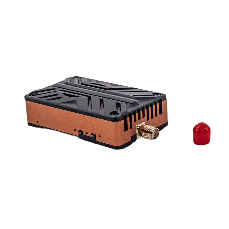
A 2.5W video transmitter is not a 2.5W heat source. That distinction sounds pedantic until you bolt a high-power RF amplifier onto a compact 27.59-gram airframe module, seal it against airflow, and discover that the number printed on the specification sheet has almost nothing to do with what the hardware can sustain in flight.
This is where a lot of FPV hardware specifications become misleading. Engineers see 2,500 mW and immediately think range. Marketing departments see 3.0–3.5W peak and print the larger number. The amplifier, unfortunately, does not care about either interpretation. It cares about junction temperature, thermal resistance, duty cycle, supply voltage, antenna load, airflow, and how quickly the enclosure can get rid of the watts it cannot turn into RF energy.
That is the real engineering problem. 2.5W Is an RF Rating, Not a Free Performance Multiplier. The transmitter operates at 5.8 GHz and provides four selectable output levels: 25 mW, 800 mW, 1,600 mW, and 2,500 mW. Under adequate cooling, peak RF output can reach approximately 3.0–3.5W.
The useful part of this specification is not the 3.5W figure. It is the power ladder. A transmitter that can move between 25 mW and 2.5W gives the flight controller something many fixed-output systems lack: a way to match RF power to the actual mission instead of continuously dumping maximum available power into the amplifier.
That matters because RF power is logarithmic when expressed in dBm. Moving from 25 mW to 2.5W is a 100-fold increase in linear power, equivalent to roughly a 20 dB increase in transmit power.
Twenty decibels is substantial. But it does not mean 100 times the usable range. Free-space received power falls with the square of distance, so the theoretical range relationship is closer to the square root of the power ratio. A 100× increase in transmit power corresponds to roughly a 10× increase in idealized free-space range, assuming antenna gain, receiver sensitivity, frequency, polarization, propagation conditions, and everything else remain unchanged.
They never do. Real FPV links live in a much uglier environment. Antenna orientation changes. The aircraft banks. The ground operator moves behind an obstruction. The airframe itself can shadow the antenna. Multipath appears. Regulatory limits may constrain the usable output level.
So the engineering value of a 2.5W transmitter is not simply “more watts = more range.” It is headroom. Here’s Where the Math Actually Breaks Down. RF amplifiers are inefficient machines. They convert electrical energy into RF energy, but the difference does not disappear. It becomes heat.
If the transmitter consumes substantially more electrical power than it radiates as RF, the aluminum housing becomes part of the thermal system. At 2.5W RF output, even an amplifier with reasonably good efficiency can leave a meaningful amount of heat inside a component occupying only 38.8 × 38.6 × 22.5 mm.
That is a tiny thermal package. Seriously, if somebody tells you that a 27.59g, high-power VTX can simply be pushed harder because “aluminum dissipates heat,” ask them for the thermal resistance and sustained-output test conditions.
Aluminum is not a cooling system. It is merely a material with reasonably good thermal conductivity. The distinction matters because heat has to travel through several physical interfaces before it reaches the surrounding air: semiconductor junction → package → thermal interface → housing → external surface → boundary layer → airflow.
Every interface introduces thermal resistance. And every degree of temperature rise reduces the margin available before the RF amplifier reaches its operating limit. The 3.0–3.5W Peak Number Needs an Asterisk. Peak output is where specification sheets become particularly slippery.
The hardware is specified for 2.5W selectable output, while peak RF output can reach 3.0–3.5W when sufficient cooling is available. Those are not equivalent operating conditions. A peak value tells you what the hardware can produce under a particular thermal and electrical condition. It does not tell you that the transmitter can continuously operate at that level.
This distinction should be mandatory in any serious UAV hardware datasheet. A 3.5W burst lasting several seconds is one engineering problem.
A continuous 3.5W output during a long flight on a hot day is another. A transmitter mounted against a carbon-fiber plate inside a densely packed fuselage is another problem entirely. Look, this is basic thermal engineering, not aerospace black magic.
If the RF amplifier produces more heat than the mounting arrangement can reject, the temperature rises until something gives: output power falls, protection activates, performance becomes unstable, or component lifetime takes the hit. The datasheet’s peak number cannot override thermodynamics.
The Aluminum Housing Is Doing Real Work. The 38.8 × 38.6 × 22.5 mm aluminum structure is not just mechanical packaging. It is part of the thermal path.
That is one reason enclosure geometry matters on a high-power VTX. The amplifier generates heat internally, and the housing provides a conductive route toward a larger surface area where that energy can eventually be rejected. But mounting changes the equation. A transmitter mounted directly against a thermally conductive structure may have a very different thermal behavior from one suspended on soft vibration-damping hardware with minimal contact area.
The same transmitter can therefore behave differently in two aircraft. That is an uncomfortable fact for anyone treating the component specification as an independent performance guarantee.
The mounting pattern is 30.5 × 30.5 mm using M3 hardware, so the module follows a common flight-stack mechanical architecture. That helps integration, but it also creates an obvious engineering trap: standard mounting geometry does not guarantee standard thermal performance.
The frame designer still has to decide where the heat goes. Weight Makes the Problem More Interesting. At 27.59g, the transmitter is relatively compact for its output capability. But engineers should stop evaluating VTX hardware purely through grams. The more useful question is:
How much RF capability does the aircraft gain per gram while maintaining acceptable thermal behavior? A high-power transmitter that weighs less but requires aggressive cooling can become a systems-level liability. The aircraft may need additional airflow, a more exposed mounting location, larger thermal interfaces, or changes to the fuselage layout.
Those solutions carry their own penalties. Aerodynamic drag increases. Packaging becomes harder. Environmental sealing becomes harder. And the designer may end up spending more mass elsewhere to support the supposedly lightweight component. This is why isolated component optimization often produces mediocre aircraft.
A 27.59g VTX is a 27.59g component. The thermal architecture supporting it is not necessarily 27.59g. The 9–26V Input Range Is More Useful Than It Looks. The DC input range of 9–26V covers typical 3S through 6S UAV battery systems. That is an integration advantage because the transmitter does not require a dedicated voltage architecture for every common battery configuration.
A 3S pack sits toward the lower end of the input range. A 6S system approaches the upper boundary. This gives designers flexibility when the same VTX platform is deployed across different airframes, but it does not eliminate power-system considerations. Higher battery voltage does not magically make the RF amplifier more efficient. The internal power-conversion stage still has to regulate the input appropriately, and the complete electrical path must tolerate the associated current and transient conditions.
Battery compatibility is therefore not the same thing as electrical simplicity. That distinction gets lost surprisingly often. IRC Configuration Is a Systems Feature, Not a Convenience Button. The transmitter supports IRC protocol configuration through the flight controller. That means output-power selection and related VTX parameters can be integrated into the aircraft’s control architecture rather than requiring physical intervention at the transmitter.
This becomes particularly useful when the four RF output levels are treated as operational states rather than four numbers printed on a box. Short-range flight does not necessarily need 2.5W. A nearby test flight may only require 25mW. A longer-range mission may justify 800mW or 1.6W.
The exact legal and operational limits depend on the deployment environment, but from a hardware perspective, the principle is straightforward: don’t generate heat you don’t need.
Running maximum RF output continuously is the electrical equivalent of driving a car everywhere with the throttle pinned. Sometimes you need it. Usually you don’t.
The Real Design Question Is Sustained Power. This is the specification I would want to see before putting a high-power VTX into a production UAV: What is the sustained RF output at a defined ambient temperature and airflow condition?
Not peak power. Not laboratory maximum. Not a screenshot showing 3.5W. Give me sustained output. Give me ambient temperature. Give me airflow velocity. Give me mounting orientation. Give me antenna load. Give me input voltage. Give me the thermal stabilization time. Then we have an engineering specification.
Without those conditions, “2.5W” describes capability but says very little about endurance. A transmitter producing 2.5W for the first minute and then thermally reducing output is a fundamentally different system from one that maintains 2.5W throughout a 20-minute flight. Both can truthfully claim 2.5W.
Only one tells you what the aircraft will actually experience. Legacy VTX Design Thinking Has a Simple Failure Mode. Older commercial design philosophy often treats transmitter power as a checkbox: 25mW for low power. 800mW for long range. More watts equals better.
That is lazy engineering. The real design variable is link margin under thermal and environmental constraints. The transmitter needs enough RF output to maintain the required link budget, but every unnecessary watt increases electrical consumption and amplifier heat. That creates a three-way trade:
Range margin ↔ electrical consumption ↔ thermal margin. Push the first upward and you generally spend more of the other two. The four-stage power architecture makes that trade explicit instead of forcing the aircraft to operate permanently at maximum output. That is the part worth paying attention to.
The 5.8 GHz Band Adds Its Own Constraints. At 5.8 GHz, wavelength is short enough that antenna placement and orientation become particularly consequential on small aircraft. The transmitter uses an MMCX antenna interface, which provides a compact coaxial connection suitable for tight UAV packaging. But the connector does not solve antenna integration.
The antenna still needs appropriate placement, impedance matching, polarization, mechanical protection, and separation from structures that can distort or obstruct the RF field. Carbon-fiber airframes are especially unforgiving.
A beautifully engineered transmitter can be installed in a terrible location and produce a mediocre link. Yes, I’ve seen aircraft with expensive RF hardware buried inside the carbon-fiber frame and then blamed the VTX when the video link behaved badly. The transmitter cannot compensate for a bad antenna installation. Physics wins that argument every time.
What the Specification Actually Tells Us. The meaningful engineering story behind this hardware is not that it produces a large number of watts. It is that a compact 27.59g module combines:
5.8 GHz analog video transmission, 40 selectable channels, Four selectable RF power levels from 25mW to 2.5W, 3.0–3.5W peak output under adequate cooling, 9–26V DC input, 30.5 × 30.5 mm M3 mounting, MMCX antenna connection, IRC flight-controller configuration, An aluminum thermal structure.
Those specifications describe a transmitter designed to be integrated into a broader UAV electrical, mechanical, and thermal system. And that last point is the one manufacturers routinely understate. The VTX is not an isolated black box.
Its power level affects battery consumption. Its amplifier efficiency affects heat. Its enclosure affects thermal transfer. Its mounting affects cooling. Its antenna placement affects the actual link. Its configuration interface affects how intelligently the aircraft manages those operating states. The hardware is only as good as the system around it. The Metric That Should Replace “Maximum Power”
If the industry wants a more useful comparison standard, stop ranking VTX hardware by peak RF output alone. Measure sustained RF output under defined thermal conditions. Then report: RF output / electrical input power / mass / stabilized temperature / ambient temperature / airflow / duration.
That dataset tells an engineer something. “3.5W peak” mostly tells a salesperson what number to put in a product title. The difference is uncomfortable, but useful.
A modern UAV does not need the biggest number on the specification sheet. It needs predictable performance after the hardware has been running long enough for the thermal system to reach equilibrium. That is when the marketing ends. That is when the engineering starts.